Here are my presentation slides from the SFS. I converted them to PDF format so anyone can view them. They have more images of the hardware and a bit more information on the process.
-
Recent Posts
Recent Comments
Archives
Categories
Meta
Here are my presentation slides from the SFS. I converted them to PDF format so anyone can view them. They have more images of the hardware and a bit more information on the process.
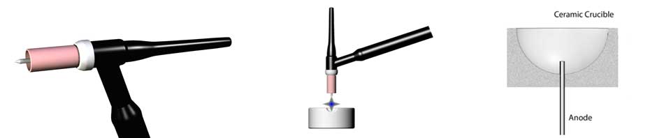
This one shows melting and casting using a consumable anode in the crucible.
Shows the melting and casting of Pd950 using a TIG torch in a argon filled glovebox.
In May 2014 I presented a paper at the Santa Fe Symposium about my experiments with the DC arc melting concept.
The paper will eventually be available from the Santa Fe Symposium website but till then.
James Binnion, James Binnion Metal Arts
Linus Drogs, Au Enterprises
This paper is an exploration of the possibility of using a DC direct arc as an alternative heat source for melting small quantities of metal for investment casting in the studio. While AC and DC arc melting are a mainstay of steel production, the small scale use of an electric arc for melting seems to be limited to laboratory “button” melters for preparing metallurgical samples.
The development of solid state inverter power supplies for welding has reduced the cost and size of the equipment needed which makes the idea of using them for small scale melting attractive.
This project grew out of the desire to melt small amounts of metal in a clean, oxygen free environment. I began to experiment with the melting of scrap to make an ingot by using a standard TIG welding torch and a graphite mold. The experiment had mixed results; some of the ingots were quite good but there was a lot more gas porosity and oxidation than I had expected. At the time I did not have time to continue exploring so I set it aside. A few years later when I began working with palladium I was frustrated by not being able to reuse the scrap in the same way I could use other metals in the shop. Again, it seemed like the TIG torch might offer the means to melt the palladium without the oxygen and hydrogen issues one gets from a oxygen/fuel torch. Since a graphite crucible was not desirable due to palladium taking carbon into solution making it brittle, some research was needed. In reading about arc melting I came across references discussing the use of metal electrodes embedded in the bottom of DC arc furnace designs, which became the starting point for the series of experiments I am presenting here.
In researching arc melting for this paper I found that the use of an electric arc to melt metal dates back almost to the discovery of the electric arc by Sir Humphrey Davy in 1801. In 1808 Davy demonstrated using an electric arc to melt a small quantity of iron. At that time the only source of electrical current available to Davy and others was the voltaic pile, Volta’s invention of the first battery. Davy used 1000 of Volta’s batteries for his demonstration of melting iron. The great expense and limited duration of arcs generated in this fashion meant that there was little development in the use of an arc for melting metal for many decades. This was changed by the invention and development of the dynamo, a mechanical electricity generator in 1867. The first designs for a practical dynamo were exhibited almost simultaneously by Dr. Werner Siemens in Germany and Charles Wheatstone in England.
In 1878 Sir William Siemens (Werner’s younger brother) demonstrated the concept of and received a patent for an electric arc melting furnace.

Figure -1

Figure-2
The invention demonstrated[1] by Siemens consisted of a crucible with either an air or water-cooled metal electrode (anode) in the bottom and a graphite or water-cooled metal electrode (cathode) in the crucible’s cover that could be raised and lowered by a mechanism to maintain the arc; this was powered by 5 dynamos driven by a 12 horsepower steam engine to provide the DC power for the experiment.
This heralded a tremendous number of electric arc furnace designs as the availability of suitable amounts of electric current continued to expand. In 1900 Paul Héroult patented the AC arc furnace which he built and installed it in La Praz, France. DC electric arc furnaces became less common once Westinghouse’s alternating current generator (licensed from Tesla) became the primary source of commercially produced electricity.
Today AC electric arc furnaces are the most common type of electric arc furnace for industrial scale work. There has been a resurgence of the DC furnace in industry in recent years as improvement in high power rectifiers have made production of DC current at suitable power levels economically viable for production of steel and specialty alloys on an industrial scale.
DC arc melting furnaces continue to be used as laboratory and small scale melting machines, typically using either a water-cooled copper crucible or agraphite crucible. One example is the button melter like the one shown below (Figure-3), which are used to melt small quantities of high purity metals in a controlled atmosphere. The other use is in small automated casting machines mostly used in dental laboratories with some use in jewelry manufacturing described by Dr. Hubert Schuster in a 2006 SFS paper[2] (Figure-4). The intent of this paper is to look at the DC arc furnace as a manual process tool more suited to the needs of a studio metalsmith.

Figure-3
Cianflone Model 2701X Arc Button Remelt Furnace

Figure-4
Orotig SpeedCast 220MJ – Pt/Pd
There are two main requirements for the arc furnace melting process: a heat source and a container for the molten metal. For the experiments in this paper the heat source is a Tungsten Inert Gas welding torch. TIG welding is a process in which the heat for fusing metal is provided by an arc struck between the work and a non-consumable tungsten electrode. The arc ionizes a stream of inert gas (argon or helium) supplied by the torch to produce an intense, hot plasma that melts the metal. The stream of inert gas shields the molten puddle from atmospheric gasses outside the arc column, while also cooling the tungsten electrode and the trailing weld puddle as it solidifies. There are a three different variations of the process defined by the type of current supplied: AC, DC Electrode Negative and DC Electrode Positive. In this experiment the DCEN configuration is the only process used. The other two styles are mostly used for aluminum welding and do not deliver the amount of heat into the work that DCEN does.
In the DCEN mode, when the arc is struck the electrons streaming from the tungsten electrode strike the positive ions coming up off the workpiece. This collision produces a release of heat energy that is carried onto the workpiece by the flow of the inert gas. This hot gas column combined with the heat energy released by the high velocity electrons striking the workpiece provide the energy to melt the work. In DCEN 70% of the heat energy in the arc is deposited in the workpiece with the remaining 30% being deposited in the the tungsten electrode.

Figure-5
TIG Torch and modified crucible
The second requirement for this process is an electrically conductive crucible or one with a conductive electrode in it. The crucibles used in these experiments are a modified version of the typical refractory melting dish used by many studio metalsmiths. The necessary modification is to drill or cast the crucible with a hole in the bottom center where an electrode can pass from outside to the bottom area of the dish. The electrode needs to be a fairly tight fit in the hole to prevent molten metal leakage. The positive terminal of the power supply is attached to the electrode to provide the electrical connection to the metal to be melted. The use of this refractory crucible is likely the greatest difference between the process described here and that of the small scale arc furnaces currently used in labs and production facilities.
Normally the TIG torch is only used to melt a small puddle of metal when used as a welding torch. The thermal conductivity of the mass of the base metal quickly draws the heat away from the puddle melted by the arc. In welding this is a good thing as you don’t want the whole piece collapsing into the molten puddle. However here we want the complete melting of all the metal in the crucible. The insulation provided by the refractory in the crucible allows the heat energy to remain concentrated in a relatively small area. The arc temperature is reportedly >10,000°K[3] so along with the I2R heating from the current flowing through the metal and the heat transfer from the electrons striking the metal, there is also considerable radiant heat from the arc. The metal charged in the refractory crucible can be melted fairly quickly as the arc deposits a considerable amount of heat into the charge.
The TIG torch is designed to hold the tungsten electrode in a copper collet to provide good electrical contact with the supply cable. The collet is surrounded by a collet holder that is externally threaded on one end to fit into the torch body and threaded on the other end to draw the ceramic nozzle into the insulator. The collet holder body is ported to allow the inert gas to flow from the torch body through the collet holder providing cooling of the torch head on its way to the nozzle which directs the flow of gas around the exposed section of tungsten and out to the workpiece. The back cap screws into the other end of the torch body closing the collet and sealing the back end of the torch body.

Figure-6
TIG Exploded View
There are two types of torch nozzle. The standard type nozzle just allows the shielding gas to flow around the electrode and out to the workpiece in a turbulent fashion. The other is called a gas gens nozzle, which creates a laminar flow of gas around the electrode and out to the work providing better shielding of the weld puddle. The nozzles come in a wide range of sizes to accommodate different work geometries. The turbulence in the gas flow from the standard nozzle caused some of the problems I had with variable results in my first experiments. This turbulent flow greatly reduces the size of the shielded area around the weld puddle or, in this case, the molten mass. Gas lens type nozzels were used in this experiment.

Figure-7
Normal and Gas Lens Nozzles
TIG torches are either air-cooled or water-cooled. The air-cooled are actually cooled by the flow of inert gas through the torch body and head assembly. The electrical supply cable and inert gas hose both fit into the torch handle. In higher amperage torches the electrical supply cable is quite large and heavy which makes manipulating the torch difficult as well as limiting the maximum amperage available in a manual torch. The second class is the water-cooled torch. This style has an additional hose going to the torch body to supply the cooling water; the electrical supply is changed to a hose with an internal cable in which the return water flows, thus cooling the supply cable as well as the torch head. This arrangement makes the torch much easier to handle due to the significant reduction in weight and increased flexibility of the water-cooled supply cable in comparison to the air-cooled variety. The reduced weight and increased flexibility make the water-cooled variety the preferred tool of many applications including this one. Both type of torches were used in these experiments: a 150 amp air-cooled torch and a water-cooled 350 amp capacity torch.
Though the TIG process can be run from almost any constant current welding power supply, it is typically run from a supply that allows for remote control of the output current level. TIG power supplies range from a bare bones supply that only has current control to very sophisticated control of the arc process parameters . For this use a basic power supply is adequate. The relatively new inverter type power supplies have greatly reduced the size, weight and cost of high current welding power supplies.
To start the torch an arc must be struck between the tungsten and the work. There are three basic ways to initiate the arc. The first option is a “scratch start”, in which the arc is initiated by dragging the tip of the tungsten across the work like same as a standard stick welding process to initiate the arc. This method can be tricky to master and is not a good method for this project as it would be close to impossible to scratch start on material such as casting grain, and restarting the arc on a molten puddle might not be possible. Second option is the “lift arc” method in which the power supply senses the short circuit condition when the tip of the electrode is touched to the work, and restricts the current to a low value. There is a small arc that ignites as the electrode lifts from the work. The power supply senses the loss of the short circuit and applies the full demand current called for by the current control to the torch, which causes the arc to reach full power. This works well for initiating an arc while the charge is still solid. However, if the arc needs to be reignited when the metal is molten, dipping the tip of the tungsten electrode into the melt contaminates it with the molten metal resulting in reduced performance of the torch. The third method is ”high frequency” or HF arc in which the arc is initiated by a secondary power supply that couples a high frequency (1-3 Mhz) high voltage 1-3 Kv low current signal onto the welding lead. As the tip of the tungsten electrode is brought towards the work an arc will jump between the tip and the work providing an ionized path for the welding current to follow. After the arc is established most DC welding power supplies will then disable the HF output. High frequency arc ignition is the preferred method for this process.
Two different power supplies were used for these experiments.

Figure-8-A
Thermal Dynamics GTS 130

Figure-8-B
Miller Trailblazer
There were several types of crucibles used in this set of experiments :
⁃These were drilled with diamond core drills to place the electrodes in the bottom

Figure-9
Fused Silica Crucible with Tungsten Electrode
To provide complete protection from undesirable gases many of these experiments were carried out inside a vacuum purged glovebox. This is a vacuum tight chamber that can be sealed and pumped down to a rough vacuum of 26-66 Pa (0.2-0.5 mm Hg) and then backfilled with the desired gas. In practice this brings the O2 level in the glove box down to about 100 ppm. Once purged the glove ports are opened to allow manipulation of items in the box using gloves sealed to ports in the box, which maintains the barrier to the external atmosphere.

Figure-10
Vacuum Purged Glovebox
There are also sample locks, small vacuum purged 2 door chambers that allow items to be transferred into or out of the glove box without contaminating the inert atmosphere inside the box. Power, cooling water, and other services are brought into the chamber via feed-through and valve sealed ports. In these experiments argon was used as the inert gas but in many cases less expensive nitrogen would work just as well. Given its size this glove box is not what I would recommend for this process in a jewelry shop or studio. It is too big for most users but it is what I happen to have in my shop. A big advantage to casting inside the glove box is that the flasks are purged of residual oxygen when being processed through the vacuum lock. This results in bright fire stain free castings right out of the investment.
The lost wax castings for this experiment were done in a slightly modified Cast/T centrifugal casting machine. The crucible cradle was removed and a cast silica funnel was put in its place to provide less restricted access to the pouring opening in the top of the machine . The second modification was to allow the machine to be used inside the glove box. Everything inside the glove box must be able to withstand being pumped down to a rough vacuum of between 66-26 Pa. The motor in the Cast/T is paired with an electrolytic run capacitor. This style capacitor has a liquid impregnated electrolyte inside it and during evacuation of the chamber the capacitor can most likely would have vented the electrolyte and both ruined the capacitor and made a mess. To prevent this from happening, the capacitor was removed from the machine and a pair of leads were added that were brought to a pair of feedthroughs in the side of the glove box wall. The capacitor was then attached to the exterior leads of the feed through so that it would not be exposed to vacuum. This seems to cause no issues with the operation of the machine but a more elegant solution might need to be found for a commercial version of the processes. A Universal or DC motor would be one solution but they would require special brushes as standard carbon brush life in inert environments is very short.
In the following experiments various combinations of anode, crucible and metal were used to test the viability of the process.
These experiments were done with a simple bronze clamp making the electrical connection to the anode.
The first set of experiments with arc melting were done in the glove box with a clay bonded silica crucible drilled for a 1/4”⌀ carbon rod. These tests were just to see if a reasonable amount of metal could be melted with the 130 amp power supply. A piece of copper rod 1”⌀ x 1” long was cut and placed in the crucible with approximately 1/4” of carbon sticking up into the crucible. The carbon rod was connected to the power supply by a standard welding ground clamp and cable. An arc was struck on the surface of the copper and a puddle formed on the surface. At first, very little appeared to happen beyond the initial puddle for several seconds then fairly rapidly the puddle grew in size and in less than a minute the copper rod began to loose form and collapsed into a molten pool. The molten copper was poured into a second crucible to cool. The melting speed was certainly rapid enough for reasonable use in a casting process. The resulting ingot was bright and clean in appearance and well formed, This ingot was remelted several times with similar results each time. On one test I shook the crucible before the ingot lost form to see what would happen if connection to the anode was lost. The high frequency pulse quickly re-established the arc, but there was a definite change in sound to a one much more like standard arc welding. In hindsight it appears that there was a second arc established from the carbon rod to the metal in the lower part of the semi molten mass. From the sound, this arc continued to exist up to the point of the whole mass melting. After the metal was poured, the carbon rod was clearly reduced in size and the crucible in the area surrounding the carbon rod was also heavily eroded with a green and black glassy appearance. Upon examination I believe in the very high temperature caused by the arc the presence of the carbon reduced the silica in the crucible to silicon carbide. However this did not appear to effect the melting of the metal but would quickly damage the crucible to a point of failure.
In this next set of experiments the crucible with the carbon anode was replaced by a crucible with a 0.125”⌀ tungsten anode in place of the carbon one.
A single chunk of copper was placed in the clay bonded crucible. The arc was struck and the melt proceeded with similar efficiency to the carbon rod experiments. There was concern that the molten metal would wet the tungsten and possibly cause contamination of the melt. There was only a very tiny amount of copper that wet the tungsten and the vast majority of the exposed rod showed no indication of any damage from being immersed in the molten copper.
This time the copper was poured into an investment mold in the Cast/T and only a fair casting resulted from the test; the casting was a little rough, The assumption is that the flask or the metal or both were too hot. The procedure for getting the flask into the glove box is quite a bit more involved than a standard casting. The flask is removed from the kiln and placed on a wire mesh rack inside the sample lock. The external door is then closed and the lock is pumped down to around 13 Pa. Argon is then vented into the lock and is equalized with the internal atmosphere of the glovebox. The inner door is opened and the flask is picked up with tongs and placed in the casting machine; then melting is commenced . This adds about 5 minutes to the normal process of placing the flask in the casting machine. There was concern that a significant loss in flask temperature would occur during this extended time between the kiln and the machine. To combat this the flask temperature was brought to 579°C (1075°F). Since the crucible is cold when the metal is placed into it and mostly picks up heat by conduction from the molten metal, there was some concern the metal might freeze as it was being poured over the lip of a crucible that was far cooler than from normal torch or induction casting, where the crucible is either heated by the flame from the torch or by I2R losses from current induced in the crucible by the work coil. To combat this the arc was held on the surface of the molten metal for a longer period of time than one would keep the torch on the molten pool when torch melting. From this and further experiments it became obvious that both concerns were unfounded. The flask, while not in the kiln for a longer period of time than normal, spends most of that time in a vacuum. Therefore the only real heat loss is from radiation as vacuum is a very good insulator. And the arc seems to put more than a sufficient amount of superheat into the metal in the period from complete melting to pouring without purposefully investing time to add more superheat. In the following experiments the flask temperature was reduced to the same temperatures that would be used if the glove box was not a part of the process. The metal was only heated to melting and then poured promptly without attempting to add superheat. These changes improved the quality of the castings.
In this set of experiments the crucible was replaced by a high temperature silica crucible. Roughly Pieces approximately 20mm square were cut from 16 Ga 316 Stainless sheet. The first attempt to melt it with the 130 amp power supply took quite a few minutes to melt this mass. The first melt was poured into a spare crucible used as an ingot mold. The metal appeared bright and clean. However, the crucible showed signs of glazing with an obvious coating of stainless steel around the exposed tungsten electrode, so it is possible there was some uptake of tungsten into the melt.. The 300 amp supply was set for 200 amps maximum current to simulate the most common inverter power supply output level. The experiment was repeated and the greater amperage greatly increased the speed of melting. This melt was poured into a flask in the casting machine and a good casting was produced. A high temperature platinum investment was used for the casting.
In this set of experiments all the anodes were connected to the power supply via a modified water cooled TIG torch with its gas feed removed and its nozzle cut back to expose the tip of the collet holder in the torch head. The crucible rested on the rim of the nozzle and the collet holder, which puts the water cooling coil as close to the point where the anode enters the crucible as possible.
These experiments used the water cooled anode assembly and a consumable electrode. These electrodes are made from the same metals as the material to be melted. The goal is to determine how many of the test metals will work with a consumable anode to eliminate any chance of tungsten being picked up in the melt.

Figure 11
Water Cooled Anode Crucible
In this experiment the anode was made from a 0.125”⌀ sterling silver rod. It was intended to be a consumable electrode with the purpose of preventing the tungsten from alloying with the melt and contaminating the casting. It was mounted with about .250” protruding into the crucible. Electrical connection and cooling water was supplied by using a modified TIG torch with the gas feed removed and a shortened nozzle to bring the tip of the collet holder into contact with the bottom of the crucible. The intent was that the water cooling would keep the anode from melting too far back into the hole in the base of the crucible. Sterling shot was placed in the crucible and an arc was struck on it. It melted promptly and was poured into the casting flask. The anode only appeared to melt about flush with the bottom of the crucible bowl. A clean, bright casting resulted from the test.
These experiments utilized the water cooled anode assembly with a tungsten electrode. The goal is to reduce the chance of tungsten being picked up in the melt by keeping its temperature as low as possible. It was mounted with about .250” protruding into the crucible. Sterling shot was placed in the crucible and an arc was struck on it. It melted promptly and was poured into the casting flask. The anode appeared to only melt about flush with the bottom of the crucible bowl. A clean, bright casting resulted from the test.
A 3”x3”x1” block of graphite was used as a crucible to test melting titanium with the 300 amp power supply set for 200 amps. A piece of 1” ⌀ x 0.75” Grade 2 titanium was placed on the block and an arc was struck on the titanium. The puddle formed rapidly and the mass melted quickly. Once molten it was poured onto a steel plate to cool. Upon cooling the metal was bright and clean. When forged the metal appeared to work satisfactorily; it was not excessively brittle. No attempt was made to analyze it for contamination but according to Kroll and Gilbert[5] titanium will not pick up large amounts of carbon from gas free grades of graphite as long as the contact time is kept low. For jewelry use, the amount of carbon should cause minimal deleterious effects; this leaves the alpha case produced on the cast piece by the titanium reacting with the materials in the investment as the bigger concern.
A large size gas lens or one with an auxiliary shield ring can be used in the shop with small crucibles to melt metals for casting or ingots without the protective atmosphere provided by the glove box.

Figure-12
1.25″ Diameter Gas Lens
This provides less protection for the molten metal; by necessity smaller amounts of metal are used to keep the metal within the shielded area. Several experiments with a large gas lens (1.25” ⌀) on the air-cooled torch and an air-cooled tungsten electrode in the melting dish were done. The resulting castings appeared as clean or prehaps even a bit better than those done with a torch.
The use of the DC arc for melting metal is not restricted to only being used in a glove box as indicated above. However for the highest quality melting a completly inert atmosphere is required. The glove box does this very well but can add $4000 or more in equipment to the cost of the melting system. There are a couple other possibilities, which are outlined below.
This looks something like the glove box but it is not vacuum tight so it can be made of much lighter gage materials and sealed with elastomer caulking; some are actually inflatable plastic chambers. The requirements are a relatively airtight chamber with glove ports and a low cracking pressure check valve to allow the purge gas to freely flow through the box. The power and water leads are brought in through simple holes sealed around the cables with a flexible non-hardening putty or tape. The atmosphere is purged of unwanted gasses by constantly flowing an inert gas or nitrogen through the chamber. Upon startup, the gas is allowed to flow for a long enough period of time to dilute the unwanted gasses to levels below 100 ppm before work in the chamber can commence. The amount of time will depend on how large the chamber is and the rate of flow of the purge gas. For our needs a vacuum purged sample lock is still needed to be able to rapidly bring casting flasks into and out of the purged chamber. The cost of the purge chamber is typically less than half of the cost of what a glove box. However the purge chamber uses a large volume of purge gas which must continue to flow during the whole time the chamber is in use. The cost of this gas will eventually erase the benefit of the lower initial price. Therefore for a system used on a regular basis, the glove box will eventually be the less costly alternative.
This concept is for a hand held melting chamber that should provide a clean inert atmosphere for melting metals that do not need the absolute purity provided by the glove box. This method will still provide the quick clean melting that the arc provides.

Figure-13
Compact Arc Melting Chamber Concept
The use of a TIG torch arc to melt small quantities of metal in a refractory crucible appears to be a viable means to produce clean castings with very little absorbed gas in the small workshop or studio environment. The high temperature of the arc will quickly melt any of the jewelry metals. Depending on the metal to be melted either the tungsten or consumable anode will work to cleanly provide conductivity to the metal while melting. In the simpler arc melter configurations the up front costs and ongoing operating expenses will likely be lower than specialty arc casting machines or induction melting/casting equipment. This concept benefits from the low cost of the inverter type power supplies now available and the lower power requirements required using the refractory crucible as well as the more efficient coupling of power to the metal being melted . In addition, casting in a glove box or purge chamber provides the benefit of low gas porosity with clean and bright castings when broken out of the investment; this is due to extremely low levels of undesirable gases in the box as well as purging the flask of those gasses from the process of bringing them through the vacuum lock into the box.
[1])Siemens, C. W. and Huntington A. K. “On the Electric Furnace” Report Of The Fifty-Second Meeting Of The British Association For The Advancement Of Science (August 1882): 496-498
[2])Huston, Edwin J. ”On Some Early Forms of Electric Furnaces” The Telegraphic Journal and Electrical Review, Volume 23 (1888): 213
3)Schuster, H., Gagliano A., “Titanium Casting and Working Process for Jewelry Manufacturing” Santa Fe Symposium (2006) : (421,434)
4)Andersson, Conny “Electric Arc Furnace Hearth Connection” United States Patent US4125737 (Nov.14 1978)
[5])Kroll, W. J. And Gilbert, H. L. “Melting And Casting Zirconium Metal” Journal of Electrochemistry Society (1949):158-169
[6])Jones, R.T., Reynolds, Q.G., Curr, T.R. And Sager, D.”Some myths about DC arc furnaces” Southern African Pyrometallurgy 2011 (March 2011)
7)Jones, R. T. “DC Arc Furnaces – Past, Present, And Future”
